Home About us Contact us Protuner Loop Analyser & Tuner Educational PDFs Loop Signatures Case Histories
Michael Brown Control Engineering CC
Practical Process Control Training & Loop Optimisation
CASE HISTORY 198
CASCADE CONTROL OVERCOMES VALVE PROBLEMS
A large petro-chemical refinery asked me to perform an audit on several critical base layer control loops.
This article deals with a problem found on a valve controlling the flow of fuel to a heat exchanger. The actual temperature control of the exchanger was accomplished by using a cascade master temperature controller that sent its output to the set point of the steam flow secondary controller. It was a very important control as a large section of the plant downstream from the exchanger was highly dependent on the temperature being at the correct value at all times. Even small temperature deviations from the desired set point value could cause problems.
The operators reported that the temperature control was working well, but the engineering supervisor had included the control in the audit because it was so important.
Why does one use a cascade control system?
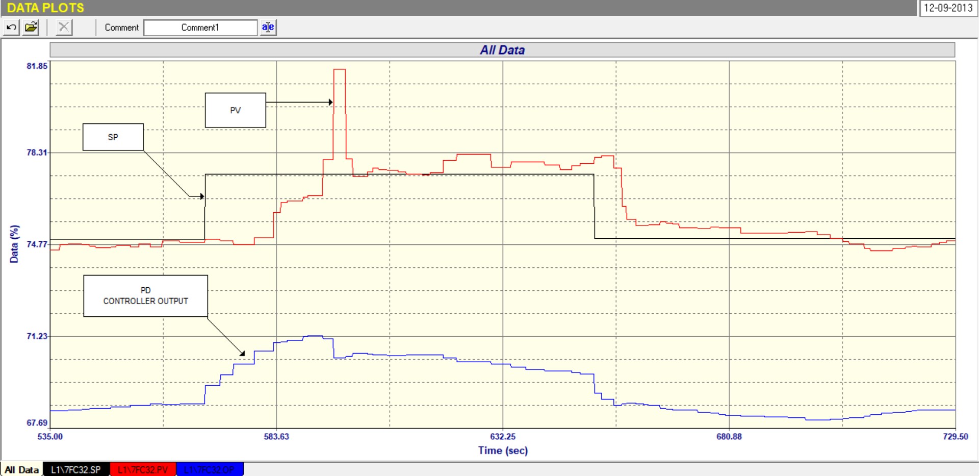
Figure 1
Figure 1 shows the schematic of the cascade control system that might be used on a heat exchanger, where the process fluid is heated by steam to a desired set point. To many people it seems strange that the output of the temperature controller (primary or master controller) does not go straight to the steam valve, but instead is routed to the set point of a flow controller (secondary or slave controller), which is now the actual device that is in charge of controlling the flow of steam into the exchanger.
There are several excellent reasons why this is a very good strategy:
1. As exhaustively discussed in my articles, valves being largely mechanical devices are “the weakest link” in a control loop, and can suffer from all sorts of problems. Typically 70 – 75% of all control valves are generally suffering from some sort of problem, such as hysteresis, non linear installed characteristics, incorrect sizing, and stickiness to name just a few. These have been discussed in detail in many of my articles.
2. In a stand-alone control loop the PD (controller output) sends a signal to the positioner/actuator/valve combination which is effectively instructing it to pass a certain amount of the product passing though it so as to satisfy the control requirements. In reality the signal merely opens the valve to a certain position that is proportional to the value of the PD, and it is by no means certain that the valve was sized and calibrated correctly so that it actually is passing the desired quantity though it. One of the main reasons that the flow control loop is incorporated, is to ensure that the correct amount of product does actually pass through the valve. If the correct amount is not achieved then the feedback controller will carry on moving the valve until the PV (process variable) does actually reach SP (set point).
3. The next reason as to why it is a good strategy is the fact that cascade control is normally used on processes with relatively slow dynamics. Now again as discussed in previous articles, a “fact of life” in feedback control is that whereas processes with fast dynamics can be controlled reasonably quickly, slow processes can only be controlled slowly. Instability will result if you try and speed up the control. This means that if the valve does not pass the correct amount of product though it, then the temperature controller can only correct for that as well in a very slow manner. Flow control on the other hand generally has extremely fast dynamics relative to slow procedures like temperature and pH, and that means that the cascade secondary flow controller can quickly get the valve to the correct position, whereas the primary controller which is there to handle the control of a generally much slower process, would on its own, take much longer to get an imperfect valve to the correct position. Therefore the cascade secondary flow loop gets the valve to the correct position relatively quickly, so the valve problem does not impact adversely on the slower temperature process.
People have often queried me as to how to go about tuning cascade loops, and there is lot of confusion on this. However it is very simple. The tuning procedure is to start with the secondary control loop. One puts the set point of the controller of this loop into Local so as it is not affected by the master controller and then one performs the normal open and closed loop tests on this loop.
Once these are complete, and if the controller is now tuned correctly, then the set point of the secondary controller is placed back in Remote which is the signal coming from the PD (output) of the master controller. Then normal open and closed loop tests are conducted on the master loop, and the tuning calculated.
I think that what confuses people is that when looking at tuning the primary loop it appears that one has to look at two controllers, two transmitters and only one valve, but in actuality just think of the secondary loop as a “complete” final control element on the output of the master controller, so when you do the open loop step tests to determine the transfer function of the process all the elements are actually included in the PV response to a PD change, and the “maths” takes care of all those different elements.
I love tuning cascade loops because I know that the cascade effectively eliminates all the valve problems, and one can rely that the reaction from the step change of PD accurately represents the true process and is generally not affected by problems in the final control element.
Figure 2
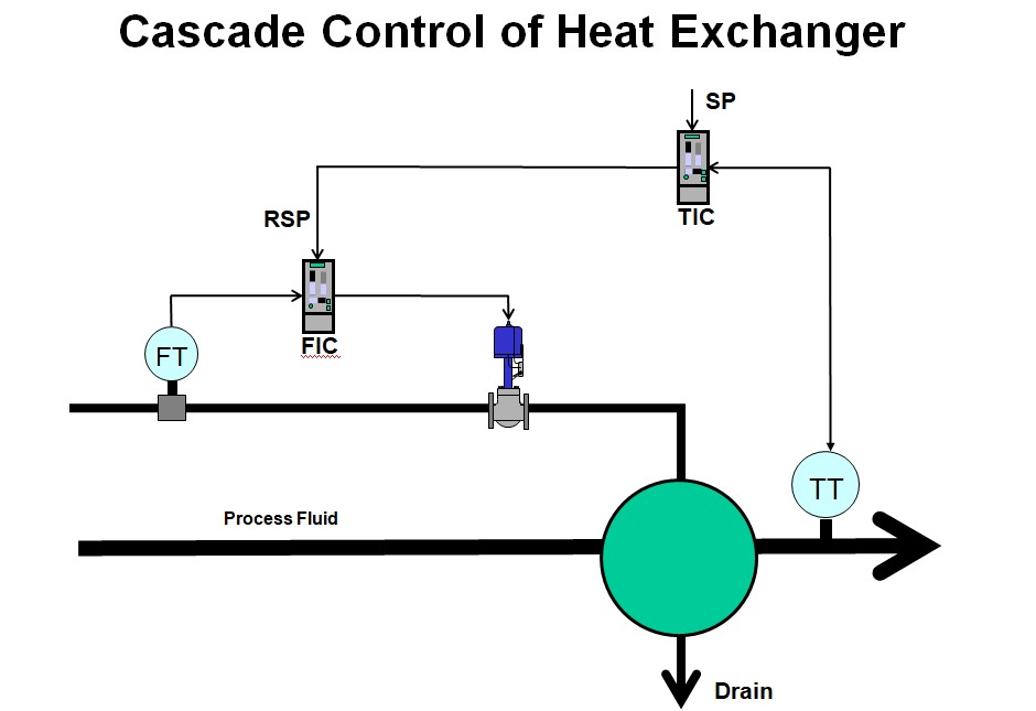
Now in the example under discussion in this article, we are going to look at the tests on the secondary steam flow control loop on the heat exchanger. Figure 2 shows the “As Found” closed loop test with the tuning that we found in the controller. and with the controller on local set point, and with SP step changes being made.
It can be seen from the figure that on the first SP step upwards the control did not look too bad with the PV getting to SP in about 40 seconds. However on the next SP step in the down position the flow didn’t really move for about 10 seconds which would indicate the valve was sticking or had hysteresis.
However again it didn’t look too severe, but the next upwards step in SP told a completely different story. This time the valve didn’t move for some 17 seconds and then it moved and the PV overshot by quite a lot during which time the PD had ramped through 4% to get it to move.
The PD then immediately reversed a little bit, and the PV jumped down below SP where it stayed whilst the PD ramped up slowly again trying to get the PV back to SP. The SP was the stepped down by 1.5% but the PV stayed where it was until the test ended with PD ramping down slowly trying to get the valve to the right position.
This test shows that there is are relatively bad problems with the final control element consisting of the positioner/valve combination. There is possibly hysteresis or stickiness and an element of instability as seen with the big valve overshoot.
Figure 3
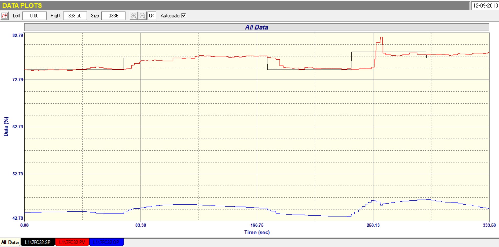
These facts were confirmed by the Open Loop Test, part of which is displayed in Figure 3. It can be seen from this test that:
1. The valve is about 2.5 times oversized (Ratio of PV change to PD change). This is not good as oversized valves multiply all faults in the valve by the oversize value.
2. There is about 2.5% hysteresis on the valve, which is not too good.
3. The valve is sticky as it takes quite a time for the positioner to get it to the correct place after a step.
4. There is a massive overshoot on steps when opening the valve. This is really bad.
5. When checking the tuning from the steps in the test, it was seen that in fact the original tuning as was found in the controller was quite satisfactory.
Figure 4
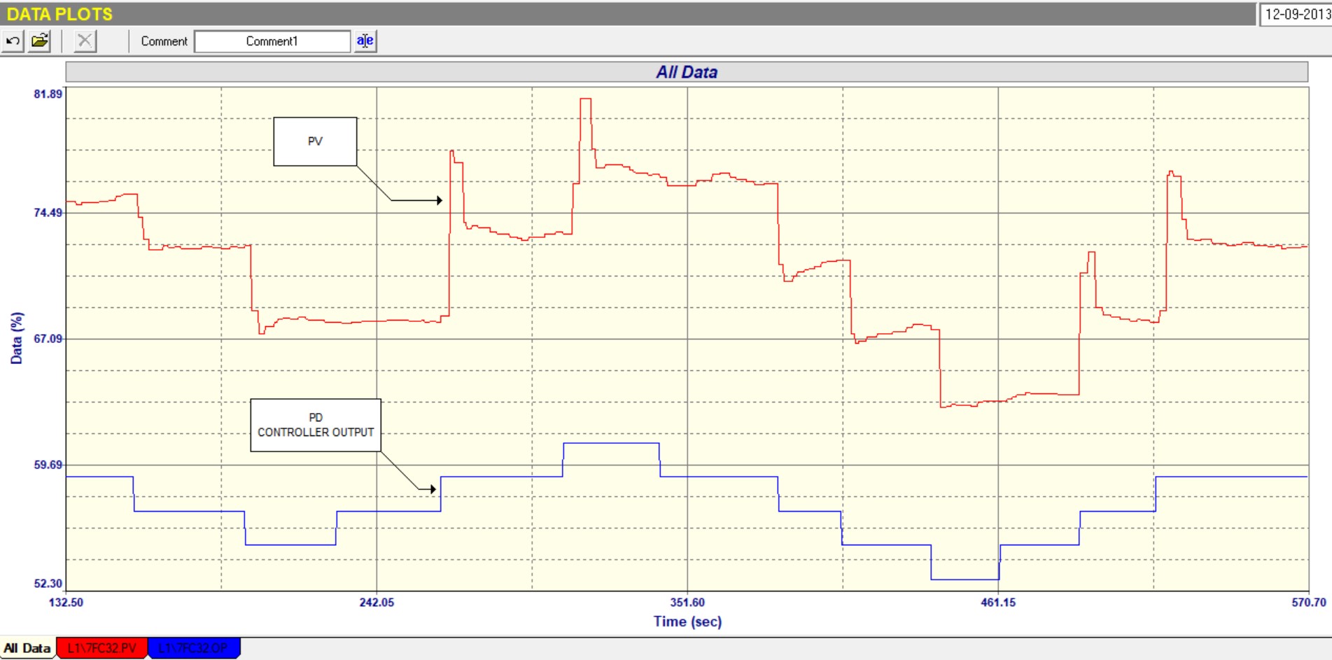
Figure 4 shows a final Closed Loop test with a slightly faster tune. However it can be seen that the control performance was very similar to that seen in the first “as-found” Closed Loop Test. Big delays can be seen when SP steps were made whilst the PD ramped up trying to get the valve to move through the hysteresis and stickiness. It also again shows how difficult it was for the controller to try and get the PV exactly on SP.
Now as mentioned above the temperature control was in fact working well even with the bad valve problems. This shows how effective the cascade strategy is. It would have been very unlikely that the temperature would ever have got to the SP if the temperature controller’s PD had been connected directly to the final control element.