Home About us Contact us Protuner Loop Analyser & Tuner Educational PDFs Loop Signatures Case Histories
Michael Brown Control Engineering CC
Practical Process Control Training & Loop Optimisation
CONTROL LOOP CASE HISTORY 145
CONTROL PROBLEMS IN A ZINC MINE
As a break from the problem reports presented in the last few Case Histories, this article will discuss some problems I encountered recently at a zinc mining plant in Europe where I carried out a base layer control loop audit. The plant has been struggling with under-recovery since the plant was built some time ago, and is investing heavily to try and improve the situation. One of the main reasons for the problems is that a lot of the plant was built using second hand equipment, and sizing of some of the equipment is far from ideal.
In general I was pleasantly surprised to find that as far as the control side was concerned that:
- The measuring instrumentation and control valves that were being used were of top quality.
- The control system is a DCS as opposed to a PLC/SCADA as usually used in mining plant. It is a very old system that will be upgraded over the next year. However as in most control systems there are completely inadequate facilities for detailed loop analysis and proper scientific tuning, which make it essential that proper tools be installed to allow optimisation to be effectively performed.
- The process control staff are really good mining engineers who had studied control and also had excellent knowledge of the process side.
- The management, process metallurgists, and control people work closely and very willingly together with the common motive of trying to improve recovery. The top plant management and metallurgists have an unusually good understanding of control problems
All these things are most unusual in the many mineral extraction plants that I have been into. In general most of the problems I encountered were more connected to process problems rather than control problems, although there is a definite need to properly optimise all the control loops in the plant.
In this article I will deal with a major problem on the level controls on a Zinc Rougher flotation bank which is
being caused by anunbelievably undersized sump feeding the bank.
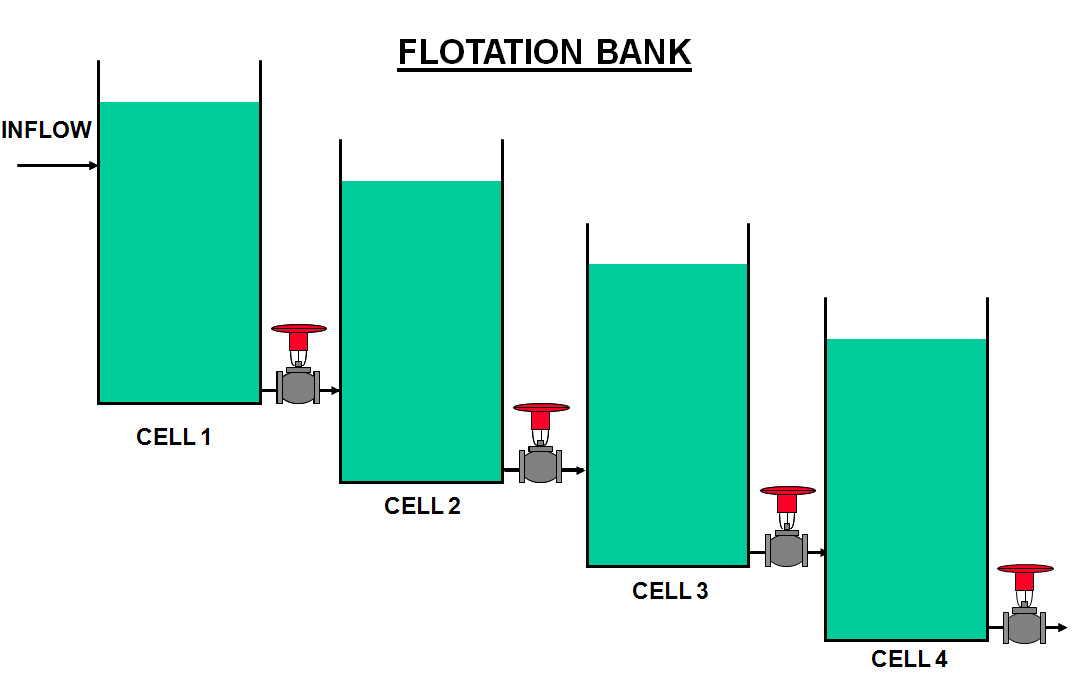
Figure 1.
As shown in Figure 1, a flotation bank consists of several tanks in series, which are fed with the slurry. The output flow from each tank is fed by gravity to the next tank via a level control valve and so-on until the end of the line. Each tank has air injected into the bottom so the air bubbles up through the slurry which is also mixed with certain reagents that cause the metals in the mix to adhere to the bubbles. The rich mixture sticking to the bubbles at the top of the tank is then drained off at the top. There are various control loops on each tank of which the two most important are the level and air-flow.
The level controls in these banks are usually the major problem, as level being an integrating process is more difficult to control than self-regulating processes like flows, and for a variety of reasons level controls tend to be very cyclic. They generally also cannot be controlled very quickly with feedback control. Here we have a whole series of tanks each feeding the next via a level control. Obviously if you get variations in the first vessel, the reaction of the level controller will be passed on to the next and so on down the line, sometimes causing ever increasing oscillations. For these reasons it is essential that the input feed to a flotation bank should be as steady as possible, and any changes that occur should be as slow as possible so the downstream controls can deal with them. To achieve this flotation banks should ideally have a large surge tank before the first cell.
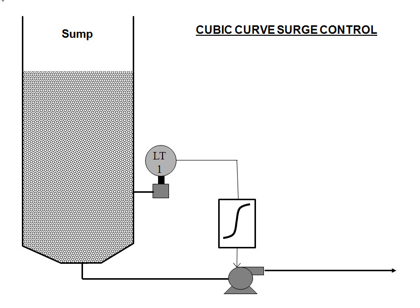
Surge tanks should be controlled so that the vessel takes up variations in the level due to changes in the incoming-flow, whilst the outgoing flow changes as little and as slowly as possible. In a case like this one does not need to use a proper controller. All that is needed is to characterise the output to the valve to achieve this objective. Figure 2 shows a suggested control scheme which works well in practice. The valve moves very little over most of the level but ensures it is closed when the level is near the bottom and is fully open when the level is near the top. (By the way, these days a variable speed pump (VSD) is used on the output of sumps instead of a valve.)
Figure 2.
The main problems in this plant were that firstly there are many surges in the milling circuits and other plants upstream from the Rougher, and secondly the sump feeding the bank is completely and utterly undersized, and was continually surging.
To try and minimise the problem the mine had installed quite a clever control scheme whereby the level controller in the sump was placed in Manual whilst the level was between 20% and 80%, so the VSD didn’t move at all. Once outside this range the controller was switched to Auto and took over control of the VSD. The problems with this scheme were that firstly the Operator had to try and judge the value of the controller output when in Manual to best balance the sump’s in and out flows. Secondly when the controller did go into automatic it had to work very quickly to prevent the sump overflowing or emptying. This resulted in terrible surges during the periods when the controller was in Auto.
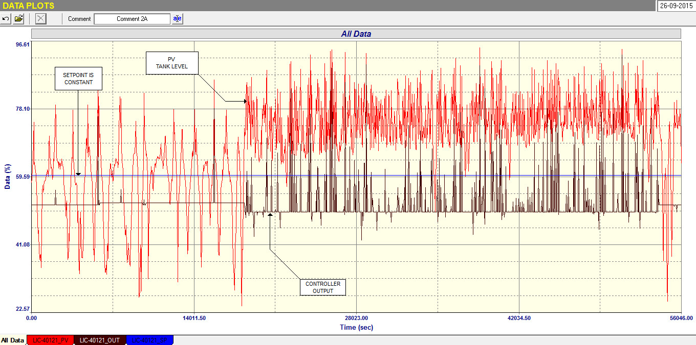
Figure 3.
Figure 3 is an extremely interesting recording of the control performance over about 15 hours. The red trace is the actual sump level which can be seen swinging rapidly up and down. The black line is the controller output. It can be seen in the first part that the Operator had set the controller output when it is in manual to balance the in and out going flow really well, with minimum switching of the controller into automatic when the level went out of the limits. However in the second part the night Operator came on and for some reason set the output down by only 2 %. This immediately upset the balance and the level went too high resulting in violent surging of the control for the remainder of the night. In the morning the day operator set it correctly again and the surging became minimal again.
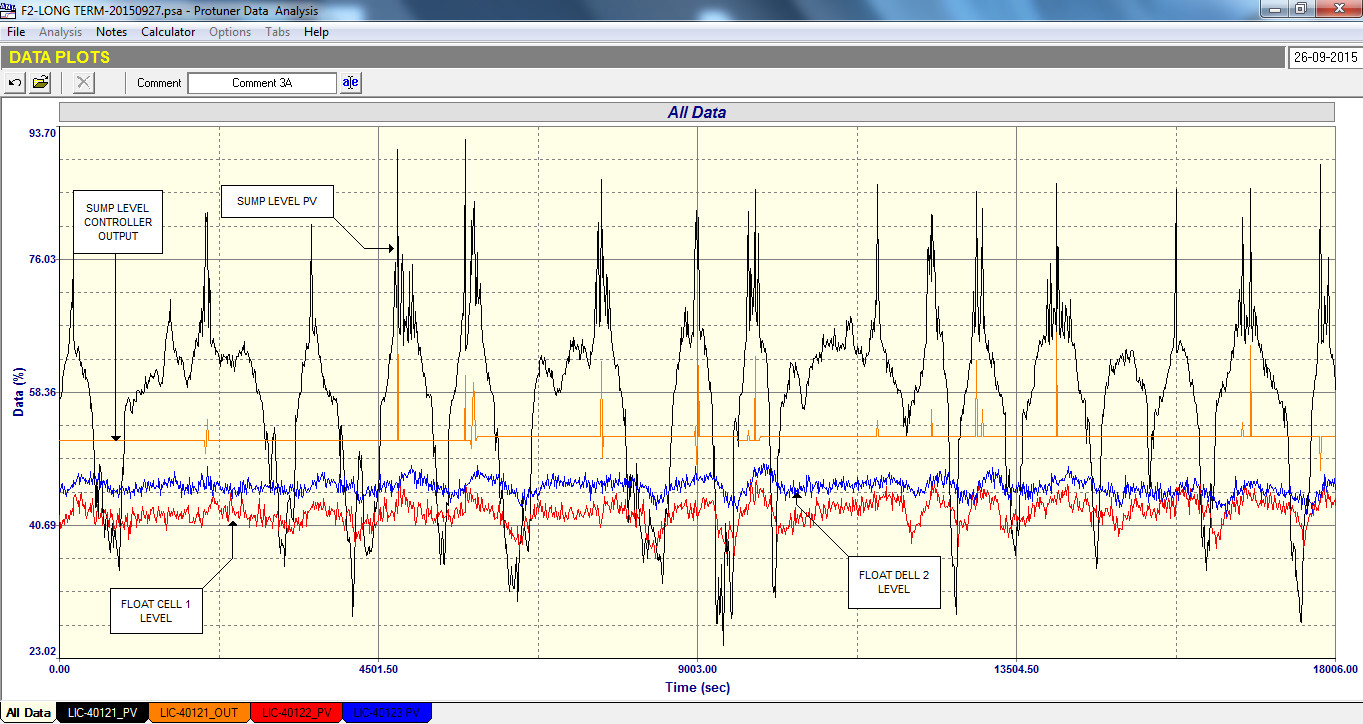
Figure 4 shows how the levels in the next two downstream float cells follow the surging, even with the surge tank level controller well balanced. The level controls on the cells had been tuned as well as possible, trying to balance the requirements to keep the levels as constant as possible whilst trying to minimise disturbances into the next vessel. This figure demonstrates clearly why it is so important to try and prevent surging into a flotation bank.
Figure 4.