Home About us Contact us Protuner Loop Analyser & Tuner Educational PDFs Loop Signatures Case Histories
Michael Brown Control Engineering CC
Practical Process Control Training & Loop Optimisation
CONTROL LOOP CASE HISTORY 162
OPTIMISING AN INTERESTING TEMPERATURE CONTROL
I have often written about the huge advantages of using cascade control on processes with very slow dynamics. It is particularly useful when it comes to most temperature processes which are normally terribly slow. The example given in this article will again demonstrate how powerful this technique is.
The case in question was an important temperature control on a distillation column in a petro-chemical refinery. The operators had been having a great deal of trouble with this control and had been controlling it to the best of their ability in manual, which was not very easy or very successful, usually resulting in them sending the temperature above and below set point in a sort of “manual limited cycle”.
The automatic control consisted of a cascade control with the temperature as the primary, and a flow as the secondary. The first thing that one must do when optimising a cascade system is to start with the secondary control loop.
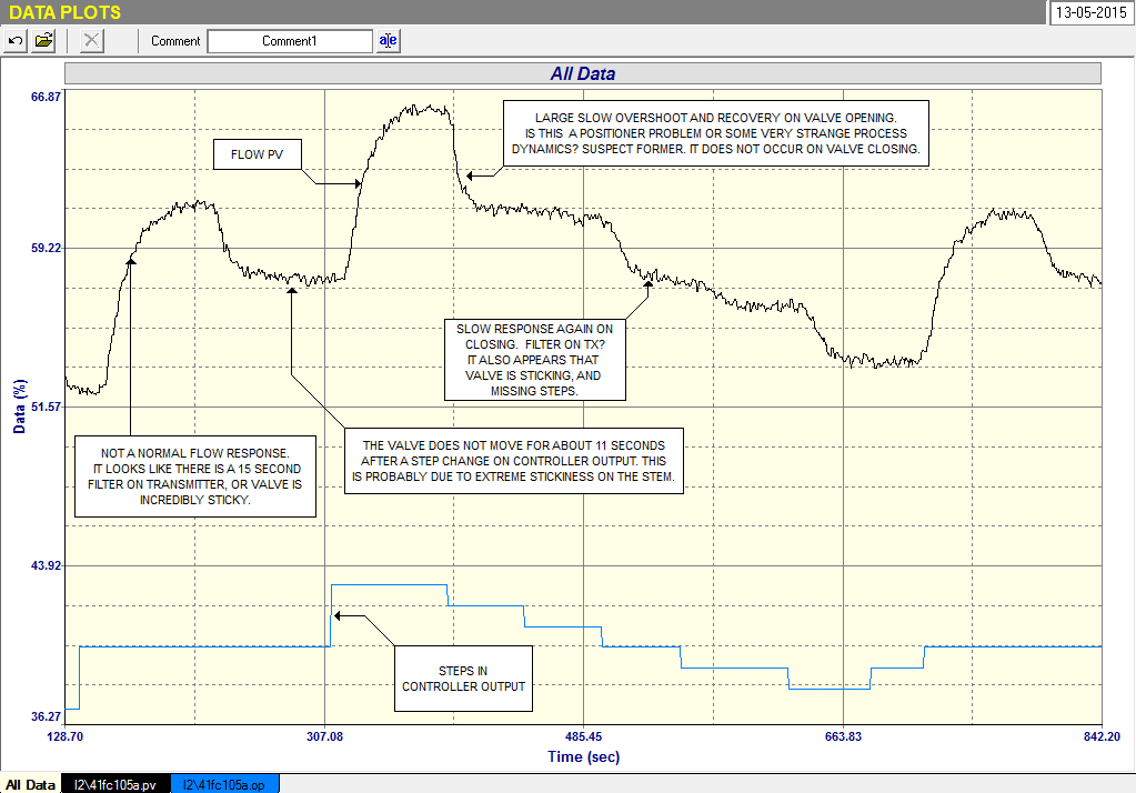
Figure 1 is the recording taken of the flow control with the controller in manual. (Open loop test). It uncovers some interesting things which are all bad:
Figure 1.
1.Comparing the relative step sizes of the input and output of the controller (PV versus PD) would indicate that the valve is probably 3 – 4 times oversized.
2. The response of the flow to step changes is extremely slow which would indicate that there is large filter on the transmitter, probably as much as 15 seconds. This is not a good practice, as filters distort information, and slow down response. Also a secondary cascade loop should be as fast as possible.
3. The valve is extremely sticky, sometimes not moving for as much as 11 seconds after a step change on the controller output. It also misses several of the small steps in the closing direction.
4. There is a huge overshoot on steps when the valve is opening, and it takes a long time before the positioner can bring it back to the correct position. This does not occur when the valve is moving in the opposite (closing) direction. This is almost certainly due to a valve/positioner problem, rather than some strange process effect.
All in all, the valve is in a very bad way and needs repair or replacement.
Frustratingly when one discovers problems like this in a plant, they normally can’t be sorted out straight away. A report in most cases is sent to the Instrument Maintenance Department who will have to schedule work on the faulty equipment. In the meantime you have to try and work around the problem as best as possible so as to keep the process working.
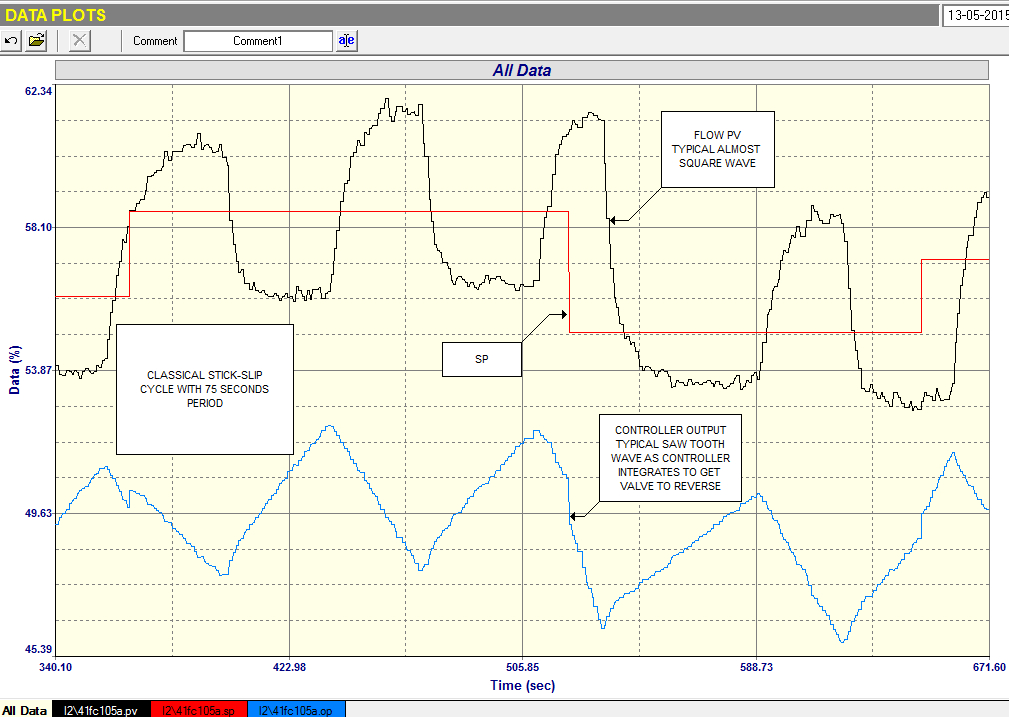
In this case the controller was tuned with a fairly slow tune to prevent instability, as the overshoot problem on opening could easily cause big problems. In this case we managed to get closed loop control working, but the loop did display a significant “stick-slip” cycle which is shown in Figure 2.
Figure 2.
Stick-slip cycles of this nature are often seen on well tuned fast self-regulating loops which are in automatic. Unfortunately the majority of people in a plant immediately say that the tuning is at fault. They do not realise that it is caused by problems in the valve/positioner combination.
Generally a cycle caused by a too aggressive tuning, cycles at about the natural resonant frequency of the loop, which in the case of a normal flow loop has generally got a period of about 6 – 10 seconds. In the case of this particular loop with the enormous filter, the period of a resonant cycle would be about 38 seconds. In this case the stick-slip cycle has a period of about 90 seconds, which is significantly slower. The resonant cycle also has a very different waveform with the cycle on both the PV and the PD (controller output) being relatively sinusoidal. In the case of a slip-stick cycle the PV has an almost “squarish” waveform, and the PD a very distinctive saw-tooth waveform appearance, which can clearly be seen in this case. These waveforms are results of the valve not responding to the PD signal from the controller, and the controller’s integral action keeps integrating until the valve does start to reverse, and it then overshoots setpoint in the direction of the reversal.
Most stick-slip cycles have an amplitude of about 2%, but in this case it was over 6% which is due to the oversized valve, and really illustrates the one of the problems caused by such valves as they amplify all the problems by the oversize factor.
We find that in many plants people don’t see stick-slip cycles because they tune the loop so slowly that the cycle stops. This is almost like stopping a cycle by putting the controller into manual, which I define as the infinitely slow tune. Loops that are tuned so slowly are basically almost completely inefficient in automatic, and cannot deal with changes effectively, so operators usually run these loops in manual anyway.
Once the cascade secondary loop is optimised you proceed with the optimisation of the primary loop. The beauty of cascade is that the secondary loops takes care of the valve problems, like hysteresis, stickiness, and non-linear installed characteristics to name a few. Therefore generally all we need to do is just tune the primary which in most cases is a very slow process.
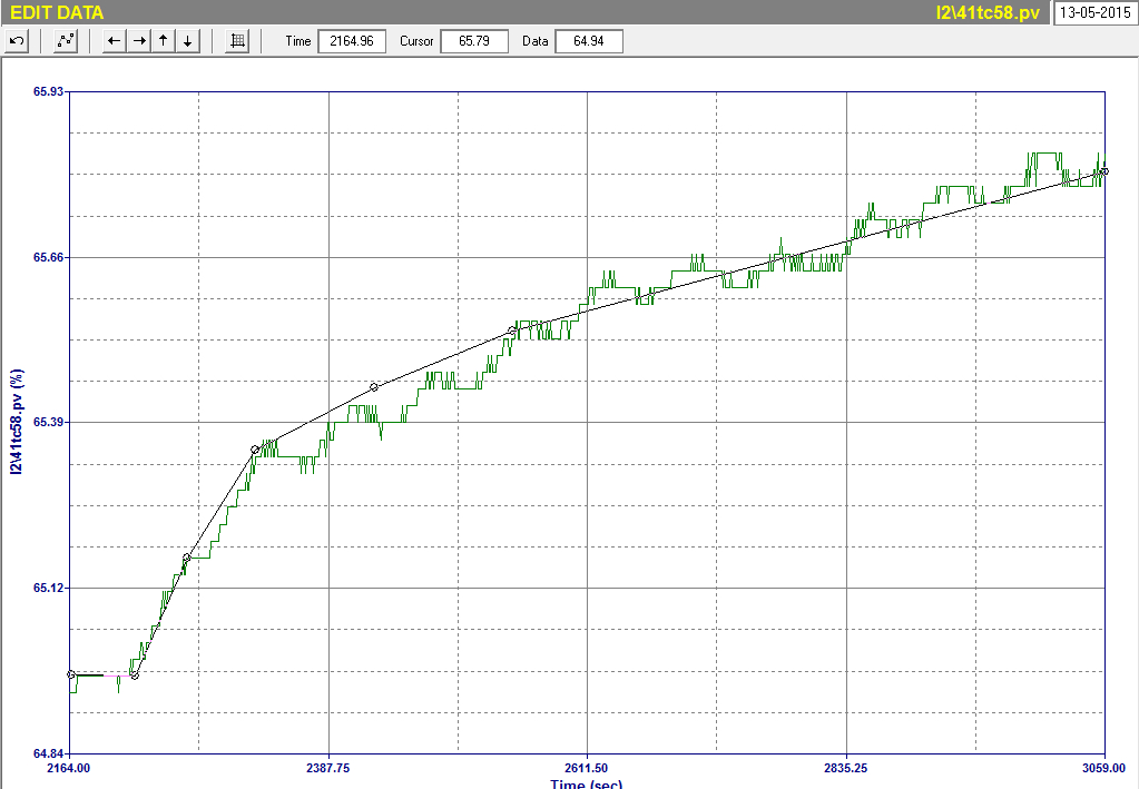
Here, we performed the open loop test on the temperature (primary), and part of the test is shown in Figure 3.
Figure 3.
This shows the process is a “positive lead integrator” the tuning of which was discussed in some detail in recent Case History 157. The original tuning was set at P = 0.75, I = 2 minutes/repeat, and D = 0.1 minutes. The new tuning is P = 6, I = 1.5 minutes/repeat, and no derivative is used. The results are absolutely magnificent.
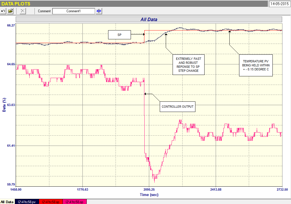
Figure 4 shows the response to a setpoint change. The response was about 12 times faster than that of the original tuning, and was highly robust, with the control keeping the temperature within ±0.15°C.
Figure 4.
This is absolutely amazing bearing in mind the terrible valve, and once again shows how the power of cascade control. It should also be noted that the large stick-slip cycle on the flow loop has absolutely no effect on the temperature, as the latter is so much slower than the flow.