Home About us Contact us Protuner Loop Analyser & Tuner Educational PDFs Loop Signatures Case Histories
Michael Brown Control Engineering CC
Practical Process Control Training & Loop Optimisation
CONTROL LOOP CASE HISTORY 174
THE IMPORTANCE OF SETTING UP YOUR CONTROLLER PROPERLY
It always amazes me that so few people really understand the workings of their feedback controllers. In my dealings over 30 years with probably thousands of people in the process control field, I have met only a couple who really understand the practicalities of the control blocks. The reasons for this are probably:
1. Most academic institutions teaching control go into the mathematics of controllers, but don’t teach anything about the practical side.
2. The manufacturers themselves who have some very clever engineers who design and build controllers, but apparently don’t seem to also understand many of the practical problems that occur in the actual field.
3. I have yet to find a manufacturer of controllers who gives a manual on their controllers and on all the different features they incorporate, that is easily understandable by the ordinary person. Many are often written by people who only understand the theory behind control and have no practical experience.
4. The manufacturers also don’t seem interested in providing training on how the actual controller works and what the various features are for. Over the years I have had engineers from some of the top controller providers and manufacturers on my courses who say they had no idea of the practicalities of controller use. I once approached several manufacturers of controllers about this, but they were not interested. One senior executive of one of the biggest manufacturers actually said that it wasn’t their job to teach people how controllers operate, even though I pointed out that each manufacturer makes their controllers differently.
Another problem that has arisen in the past few decades is due the introduction of feedback controllers into PLC systems. Previously to this controllers were built by companies that had specialised in process control over many years and had a good understanding of feedback control in the plant. They incorporated this knowledge into their DCS systems when computerised control came into being. Even to this day I seldom find many problems with controllers on these systems. They incorporate all sorts of safeguards to prevent users from programming and using controllers incorrectly. However PLC’s came from manufacturers of logic ON/OFF control systems and they had, and even many today, have little understanding of feedback controllers.
Most PLC controllers have to be set up by the user who incorporates a basic control block into the PLC programme. There are usually few safeguards and as previously mentioned people who do the PLC programmes usually set up the controllers badly. The first thing I always do when doing work in a plant using PLC control systems is to check the workings of the controllers. I find that over 85% of the plants using PLC controllers have set them up incorrectly. This results in bad control, or even no control. (I always remember one large platinum concentrator using PLC controls that effectively ran in manual for 8 years because the controllers actually didn’t operate correctly in automatic). Many are set up incorrectly so that scientific tuning is not possible.
In recent years a few of the PLC manufacturers have started incorporating actual DCS software from their DCS divisions into their PLC’s. Generally these PLC control systems work much better but even so they still leave things open for the user to play with, or set default settings incorrectly so the users run into problems. The example given below is of such a control system in a very well known and popular make of PLC.
The actual plant was for mineral extraction processing. Two serious problems were occurring:
a. When a controller is in manual it is desirable if not actually necessary, to prevent bumps from occurring when switching back to automatic. This known as “bumpless transfer”. In the plant in question, what happened was that the controller switched its output immediately to zero when the switch occurred, and then automatic control took over. This can and did cause serious problems with huge bumps often occurring on switchover. In another plant I was once working in, it actually caused an explosion as the valve was never supposed to close.
In this case it made tuning of slow level loops extremely difficult as one must perform an open loop test to obtain the tuning parameters. If you then switch to Auto and the valve closes it can literally take hours for the controller to get the process back to setpoint.
To get around this, the manufacturers generally have a tracking device on the output that ensures that the output stays where it is when the switch occurs, and thus prevents such a bump.
b. Most manufacturers also incorporate a “balanceless” feature that prevents bumps due to the fact that the PV (process variable)might not be at SP (setpoint) when switching to Auto. This basically prevents the proportional action from acting on the switchover, and allows the controller to bring the PV back to SP under the integral action alone. A further enhancement can be made by using a feature generally referred to as setpoint tracking. This immediately switches the SP down to the PV value when the controller is put into manual. Of course it is then necessary to get the SP back to the correct value when the controller is put back to auto.
In an example in this plant of a very difficult and slow level loop in the plant, the operators had great trouble in trying to control the level. Firstly most of the time there were huge surges occurring with the flow into and out of the tank where the valve would at be at an extremity of fully closed or open. Obviously control is impossible under these conditions. However in the periods where the control could operate it was also cycling badly. It was found that the tuning was completely wrong.
Again it was extremely difficult performing tuning tests due to the bad controller setup, but we did mange it by using some tricks, but it still took the best part of a day to accomplish this. If the controller had worked properly the job would have been done within an hour.
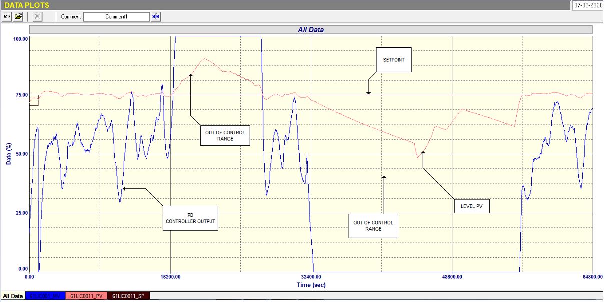
Fig.1
Figure 1 shows the final closed loop test with good tuning. It can be seen in the test which was recorded over an 18 hour period that control was only possible in 3 places where the valve could control the flow to keep the level constant. It does show that when the surges stopped how quickly the controller could get the PV to SP and hold it there in spite of quite large load changes going on all the time. Once again it is impressive how well feedback control can work if properly applied.
TEST YOUR ANALYTICAL SKILLS
I have done this once or twice previously where I invite you to test your skill in problem solving.
The example here is of a simple flow loop. (It has nothing to do with controller setup).
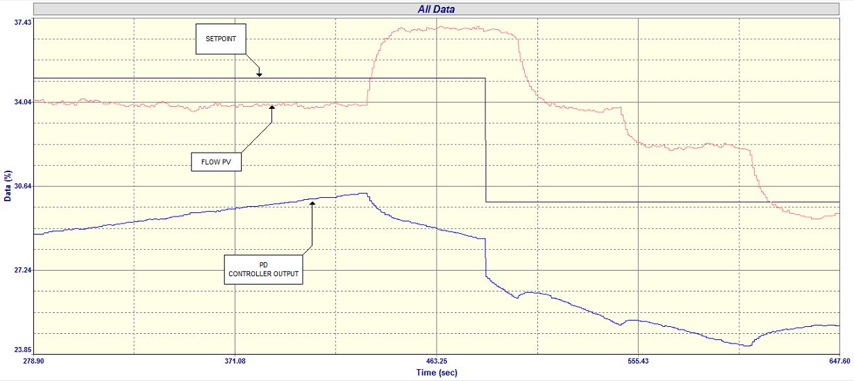
Fig 2.
Figure 2 is a closed loop test with the controller in automatic with the original tuning (which was P gain = 0.3 and I = 30 second/ repeat). In the test a single SP change was made.
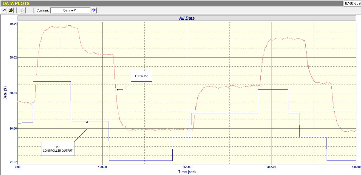
Fig.3
Figure 3 is the open loop test (in manual). As you can see in it, several steps were made on the PD.
Can you deduce the problems that were found from these?
If you wish you can email me your conclusions at michael.brown@mweb.co.za. I will give my conclusions at the end of the next Case History article which will be published in 2 months time. I will also include a long term trend showing performance before and after tuning.