Home About us Contact us Protuner Loop Analyser & Tuner Educational PDFs Loop Signatures Case Histories
Michael Brown Control Engineering CC
Practical Process Control Training & Loop Optimisation
LOOP SIGNATURE 29
AVERAGING OR SURGE LEVEL CONTROL
In many previous articles in this series and in the Case History series many examples of level control have been given, including how to tune level loops. In all these cases the tuning has been for a reasonably fast tuning. This is sometimes referred to as “tight control”.
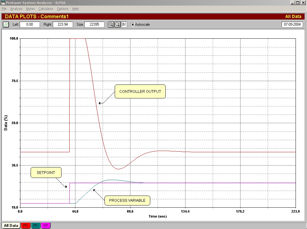
Figure 1
An example of a level loop tuned this way, and responding to a step change in setpoint is shown in Figure 1. Generally because of the low process gains inherent in level processes, one needs relatively high controller gains in order to get a fast response. In the test shown in Figure 1, the controller had a gain of 10. Therefore when making a step change in setpoint the output of the controller will immediately give a big step, and in many cases will immediately fully open or close depending on the situation.
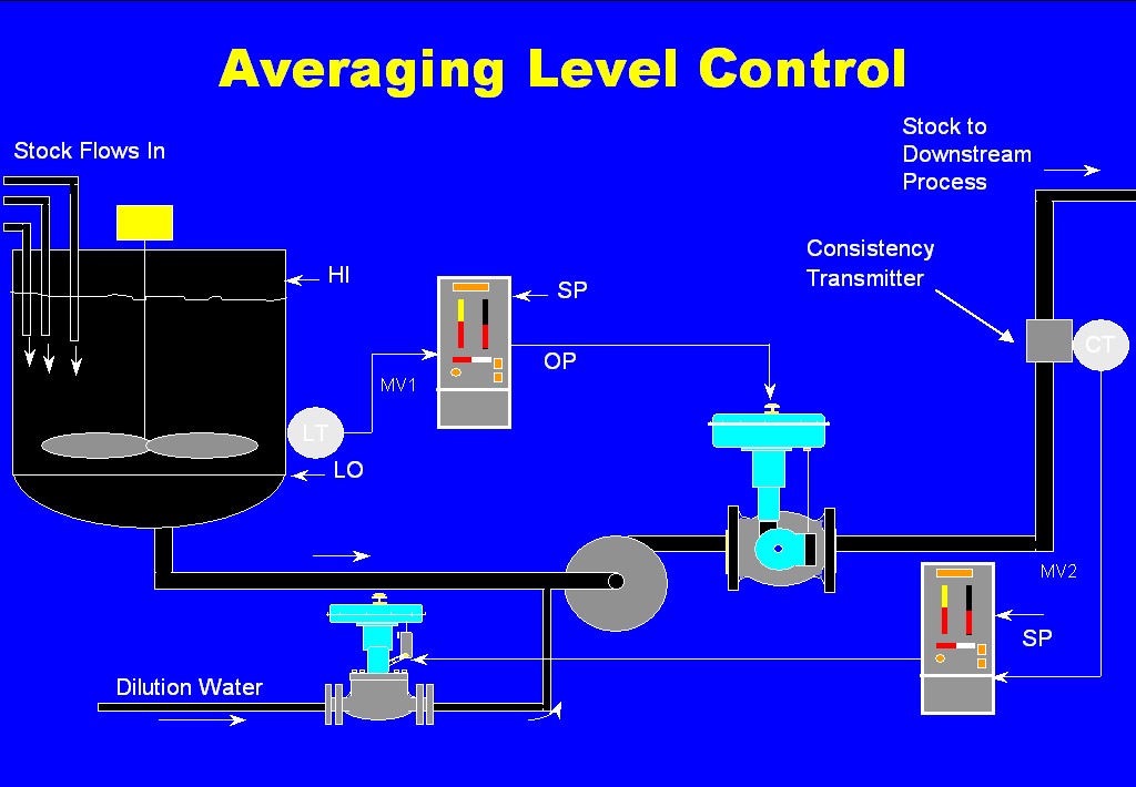
Figure 2
There are many processes in various plants where it is very undesirable for the load to suddenly change quickly. An example taken from the paper industry is shown in Figure 2. A blending tank is shown where the various pulp stocks used in the recipe for a particular type of paper are mixed. The blended mixture is pumped out of the tank to the next stage in the paper making process. Downstream from the pump there is a transmitter measuring the consistency of the pulp. This transmitter feeds a controller that controls the consistency of the pulp by adjusting a water dilution flow into the pipe before the pump.
Good consistency control is important in paper manufacture. To help achieve this (and also for some other reasons which are not important to this discussion), it is desirable that the flow of pulp out of the blending tank be held as constant as possible. If the flow was to jump around it would be very hard for the consistency control to keep up.
A valve downstream from the pump is used to control the level in the blending tank. Now if its controller was tuned with a high gain like around 10 as in the example shown in Figure 1, the chances are high that the valve would move around quite a bit, and the consistency would then probably suffer accordingly.
Now in the case of a blending tank, it is not actually important to keep it controlled at a particular point. It will not affect things if it moves around. In fact it is actually far more important to keep the flow out of the tank constant, rather than control the level. So why do they use a level controller? Why not put a flow controller in instead?
The answer to this is because of two reasons. Firstly the blending tank must not be allowed to overflow, and secondly it must not be allowed to run empty, which would result in pump cavitation. To achieve this and allow some safety factors we could then specify the control requirements as:
-
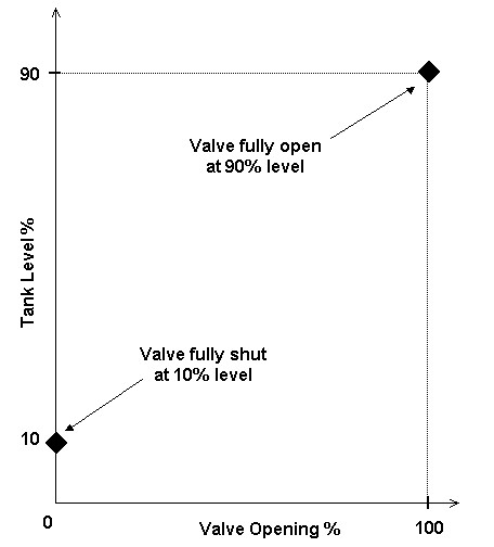
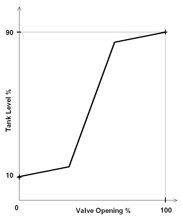
At 90% level, the valve must be fully open.
-
At 10% level, the valve must be fully closed.
-
In between these levels the valve should move as little as possible.
Figure 3
The first two requirements are shown graphically in Figure 3.
To try and achieve all three requirements, many of the manufacturers have come up with a variety of relatively fancy controllers. Some of them like notch gain controllers, error squared on gain controllers are standard blocks in many of the DCS’s. However as very normal, they give little information on their use, and I have found very few people who know what they are for, or how to use them. I am typically asked how one tunes such a controller.
In my opinion one should generally not use a controller at all for surge control if possible. (The one exception may be in cases where integral is needed to bring the level slowly back to a particular level). In fact I believe controllers used in this application in reality create a great deal of confusion amongst plant operating personnel. The reason for this is that you do not actually want to control at a particular setpoint. So if you do set the controller up properly, the chances are that the process will never be at setpoint, and this worries most operators. They have been trained to believe that a controller is only working correctly if the process is on setpoint. So what happens in most plants I have been in is that they complain to the Instrumentation and Control department, and an instrument technician or mechanician goes out and retunes the controller to operate quickly, thus destroying the desired control strategy. (As mentioned in previous articles I have found that the average instrument technician and mechanician do not themselves really understand the process and the control requirements).
What I would suggest is that the controller be dispensed with entirely, and that the operator be provided with a level indicator only. If it is absolutely essential that he should be able to control the level valve in manual if he needs to, then an auto/manual “hand station” can also be provided.
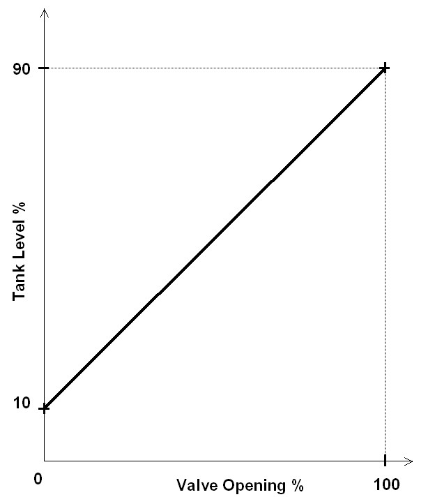
Figure 4
To achieve the control requirements one connects the valve to the transmitter via a curve-shaping block (like a polynomial or a “look-up” table). The simplest method of programming the block is by joining the 2 end points by a straight line. This is shown in Figure 4. Basically it works just like a ball valve that operates between 10% and 90% of the tank level. Thus if the level rises the valve starts opening until it is fully open at 90%, and visa versa for falling level.
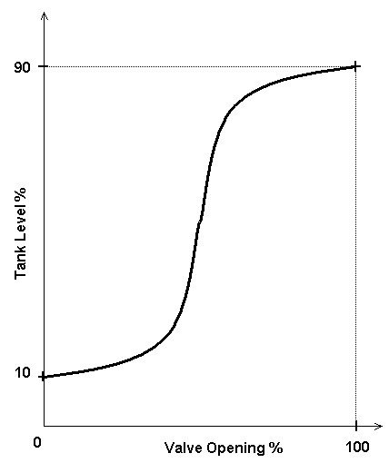
Figure 5
This is still not good enough in some applications where the valve movement may be still too much if largish load changes occur. One method of overcoming this is to use a non-linear relationship in the shaping block, instead of a straight line. One simple method is to use a graph like the one shown in Figure 5. (This type of shape is sometimes referred to as “notch gain” control). With this method the valve will move very little over most of the tank level, but will move more quickly when the level starts reaching the extremities.
Figure 6
Another method which is also very effective is to use what is sometimes referred to as an “error cubed” shaped graph, which is illustrated in Figure 6. This is similar to the notch gain, but has a much smoother transition from slow to fast. To calculate the graph, one takes the cube of the deviation from 50% level.
True Averaging Control
In certain cases one would like to retain the surge control strategy, but would like to get the level to move back slowly towards a certain level when quiet conditions with no surges exist.
The best strategy in this case is to go back to using a P+I controller with setpoint set to the desired level. However the tuning is changed as follows:
Divide the level into equal increments and use what is known as "gain scheduling" on the controller. This done by inserting different tunes into the controller, each one of them assigned to work in one of the segments. Thus you use very slow tunes in the middle of the tank getting progressively faster as the level rises or falls into the next segments. The tunings can be set to give response speeds that follow one of the curves above as desired.
This is a very effective way of performing averaging control.
Warning: Remember that on an integrating process one must change the I term when the P term changes in accordance with the "SWAG" rule "Kp x I x PG = Constant" discussed in Loop SIgnature 27. If you don't adjust the I when Kp changes you can get instability or poor response.